IEEE C37.94 – “IEEE Standard for N times 64 kilobit per second optical fiber interfaces between teleprotection and multiplexer equipment” – solves a specific, critical problem in power grids: connecting protective relays to communication equipment without copper.
The name is unwieldy but precise. It defines an optical interface, at multiples of 64 kbit/s, specifically between teleprotection equipment and the multiplexers that carry its traffic onward.
Why fiber for teleprotection
Teleprotection carries trip commands between substations – “fault detected, open the breaker now”. The command has to arrive in milliseconds, and it has to be right: a missed command leaves a fault energised, and a false one opens a healthy line.
In a substation, copper links are exposed to exactly the conditions teleprotection exists to handle. A fault produces ground potential rise of kilovolts between stations, induced transients on every conductor and severe electromagnetic interference. The medium fails precisely when the message matters most.
C37.94 replaces copper with a standardised optical link: galvanically isolated, immune to induced interference, and fast. Why galvanic isolation matters covers the underlying property; C37.94 is what turns it into an interoperable interface rather than a bespoke one.
What the standard actually specifies
Three things, and knowing which is which prevents most integration surprises.
Wavelength, optical power and receiver sensitivity — multimode at 850 nm in the base specification, which is why C37.94 links are typically short and stay inside the substation rather than running between them.
Data is carried in multiples of 64 kbit/s, from 1 to 12 channels (N = 1–12). The number of channels is negotiated between the two ends and has to match.
So that a relay from one manufacturer and a multiplexer from another actually mate.
What the standard does not define is the long-distance transport. C37.94 gets the signal from the relay to the communications equipment; getting it to the next substation is the multiplexer’s job, over whatever the utility’s network happens to be.
The surrounding standards
- G.703 – the ITU standard for the physical and electrical side of digital telecom interfaces; G.704 adds the frame structure.
- E1 – the classic 2048 kbit/s telecom interface, G.703 electrical carrying G.704 frames, still the backbone of many utility networks.
- SDH and PDH – the multiplexing hierarchies that E1 feeds into.
- SyncE – Synchronous Ethernet, the modern way to carry the same synchronised traffic over Ethernet infrastructure.
G.703, G.704 and E1 are explained here.
Why converters exist
Utilities rarely run pure C37.94 end to end. The relay speaks C37.94 because that is the standard for the relay interface; the network between substations is E1 over SDH, or increasingly Ethernet. Something has to bridge them, and that something has to preserve the timing.
Timing is the reason this is harder than it looks. Teleprotection is synchronous and latency-sensitive, and a trip command that arrives late is a command that arrived too late. A converter cannot simply repackage the bits; it has to carry the synchronisation through the transport, which is why SyncE exists as an option and why ordinary Ethernet is not one.
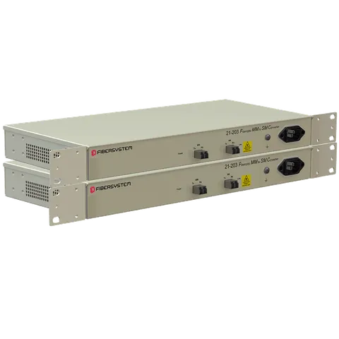
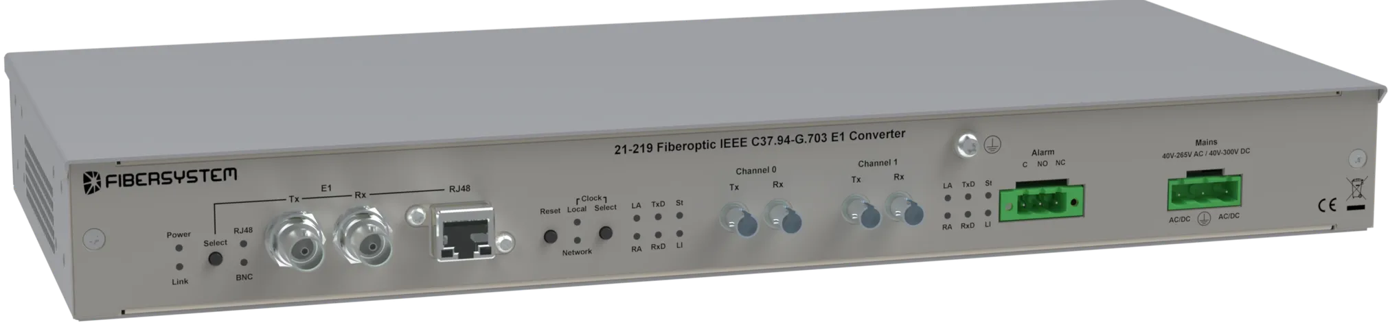
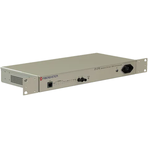
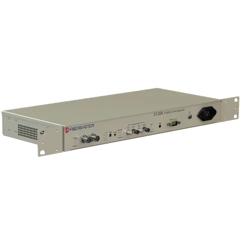
Fibersystem’s converter family covers the common bridges:
- G.703 Codir to IEEE C37.94 converters in multimode and singlemode
- IEEE C37.94 to G.703 E1 converters and multiplexers, mapping optical ports into the E1 frame for onward SDH or PDH transport
- C37.94 and E1 over Synchronous Ethernet where the backbone is modern but the endpoints are not
- Fiber optical trip links for direct transfer trip up to 240 km
What to check when specifying
Both ends must agree. A 12-channel relay interface and a 4-channel converter will not interoperate.
C37.94 is multimode in the base specification. If the link needs to leave the building, the conversion to singlemode happens at the converter, not at the relay.
Every conversion adds delay. Protection engineers work to a total budget for the trip path, and converters have to fit inside it — ask for the figure rather than assuming it is negligible.
In a synchronous chain, something has to be the master clock. Establish which device that is before commissioning rather than during it.
Related reading: teleprotection and trip links for the direct transfer trip case, and OT protection for the wider substation picture.