New networks are Ethernet – but the installed base of critical infrastructure still speaks E1. Substations, teleprotection systems and legacy defence links are engineered around it, certified around it, and will run for decades more. Understanding the trio G.703, G.704 and E1 is understanding half of utility communications.
The three names, untangled
They are routinely used interchangeably, and they are three different things.
G.703 is the ITU standard for the physical and electrical characteristics of digital telecom interfaces: voltages, impedances, pulse shapes, line codes. It defines how the bits look on the wire.
G.704 is the frame structure on top: how the bit stream is divided into timeslots, and how a receiver finds the frame boundary. It defines how the bits are organised.
E1 is the workhorse combination: a G.703 electrical interface carrying G.704 frames at 2048 kbit/s – 32 timeslots of 64 kbit/s each. It is the European counterpart to the American T1.
Two timeslots do bookkeeping. Timeslot 0 carries framing and alarms; timeslot 16 traditionally carries signalling. That leaves 30 usable 64 kbit/s channels, which is why E1 capacity is often quoted as 30 rather than 32.
“Codirectional” (Codir) G.703 is the variant where data and its 64 kbit/s timing travel together on the same pair. It is common in substation equipment and is not interchangeable with the contradirectional variant, where timing is supplied separately — a mismatch here is a frequent and frustrating integration fault.
Why it refuses to die
It is tempting to read E1 as legacy waiting to be replaced. That misreads why it is still there.
A timeslot is available every 125 microseconds, always, whether or not anyone is using the others. Protection engineers rely on that. A packet network offers an average with a distribution behind it, and a distribution has a tail.
Timing is carried by the link itself rather than recovered by a protocol on top. For teleprotection, where a command’s arrival time is part of its meaning, that is not a detail.
A relay installed in 2010 is middle-aged. Replacing the communications layer means touching protection schemes that were commissioned, tested and certified as a system.
Nothing fails less often than technology that has been running since the 1980s and has had every failure mode found already.
None of this argues against Ethernet. It argues for expecting both to exist in the same network for a long time, and for planning the boundary between them deliberately.
Carrying E1 securely over fiber
Copper E1 inherits every problem copper has in a substation: interference, ground potential rise during exactly the faults the system exists to handle, and susceptibility to interception. Galvanic isolation removes all three at once, which is why the interfaces get moved onto fiber even when distance does not require it.
Fibersystem’s converter family covers the usual bridges:
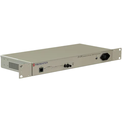
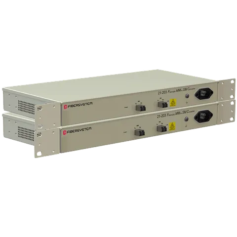
- G.703 Codir to IEEE C37.94 converters for teleprotection, in multimode and singlemode
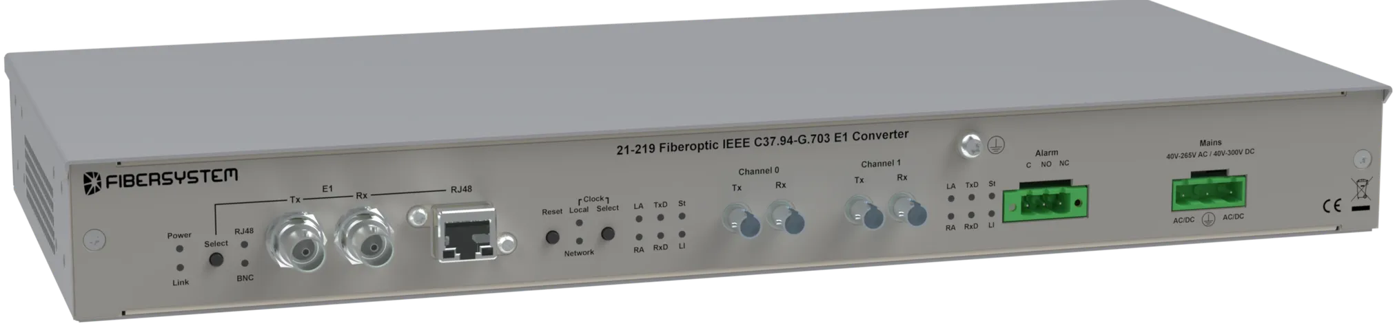
- IEEE C37.94 to G.703 E1 converters and multiplexers, mapping optical ports into the E1 frame for onward SDH or PDH transport
- C37.94 and E1 over Synchronous Ethernet when the backbone is modern but the endpoints are not
Where the timing goes
The single most common integration failure in these networks is not electrical — it is timing.
E1 is synchronous, which means something in the chain is the master clock and everything else follows it. When an E1 island is bridged onto a packet backbone, that clock has to be carried across, or the two ends drift apart and the link produces slips: occasional, intermittent errors that look like a cable fault and are not.
SyncE – Synchronous Ethernet – exists precisely to solve this, distributing timing at the physical layer of an Ethernet network the way E1 always did. It is the reason a C37.94-over-SyncE converter is a different product from a generic media converter, and the reason substituting one for the other does not work.
Before commissioning, establish which device is the clock master, how timing reaches every segment, and what happens when the master is lost. It is a fifteen-minute conversation that prevents a class of fault which is genuinely difficult to diagnose afterwards.
Related: IEEE C37.94 explained for the relay interface, and teleprotection and trip links for the direct transfer trip case.