Standard
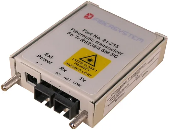
Fiber Optical Transceiver RS-232/422 D-sub
- Wavelength
- 1310 nm
- Connector
- SC
Product no 60-00-7753 (21-215)
Public sector
Vibration and a 40-year installation lifetime set the requirements, not the data rate.
The problem
The 15 kV 16.7 Hz contact line and the return current in the rails create an electromagnetic environment and earth potential differences along the track that make copper between interlockings and objects unsuitable. Fiber in the containment along the track is the standard carrier.
How it is built
Where the isolation boundary sits is a design decision, not an installation detail.
See the full patternIn the catalogue
Built from: Fiber Optical Transceiver RS-232/422 D-sub 60-00-7753 (21-215).
Standard
Product no 60-00-7753 (21-215)
Reading and references
Named customer references are not published. What we can show is the solution area this environment belongs to, and the reasoning behind the design.
Environments
The technology is the same; the buying process usually is not.
Next step
If yours is close to this one but not the same, that difference is usually where the design decisions are. Tell us what it looks like.
Verified credentials
All certifications